1 Purpose and Functions
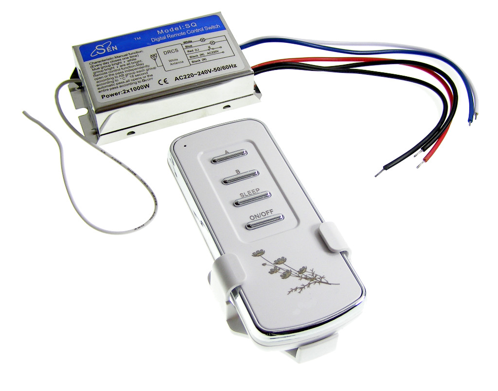
The ACTii AC9114 wireless switch is a two-channel radio controller designed for remote management of electrical devices powered by 230V. The device allows for convenient switching of receivers such as lighting, motors, fans, or audio-visual equipment using the included remote. Thanks to coded signal transmission, the system is resistant to interference and allows for the use of multiple sets in one facility without the risk of mutual control.
Key features:
- ✔ Wireless radio-controlled switch
- ✔ Two independent control channels
- ✔ High output power: up to 1000W per channel
- ✔ "Sleep" function – delayed shutdown of approximately 18 seconds
- ✔ Coded transmission to prevent interference
- ✔ Robust ABS and aluminum construction
- ✔ Includes a dedicated wall mount for the remote
Application:
The device is ideal for controlling lamps, ventilation systems, electric motors, electronic locks, as well as door and window controls. It can also be used to switch audio and video signals.
2 Technical Specifications
| Number of channels | 2 |
| Power supply | 230V AC (200 - 245V) 50/60Hz |
| Output power | 2x 1000W |
| Transmission range | Up to 20m indoors, up to 100m outdoors |
| Operating frequency | 433 MHz |
| Remote battery | 1 x 23A 12V (included) |
| Material | ABS, Aluminum |
| Switch dimensions | 81 x 44 x 21 mm |
| Remote dimensions | 103 x 45 x 17 mm |
| Product weight | 125 g |
| Certificates | CE, ROHS |
3 Installation and Connection
NOTE: Work on 230V electrical installations should be performed by a person with appropriate electrical qualifications. Before beginning installation, always disconnect the power supply.
Wiring diagram:
- Black (N): 230V neutral wire for the switched device (receiver).
- Black (N): 230V neutral wire for the switch itself.
- Red (L): 230V live (phase) wire powering the switch.
- Blue (L): Output live wire for channel 1 (receiver 1).
- White (L): Output live wire for channel 2 (receiver 2).
In standard electrical installations, the neutral wire (N) is typically blue, and the live wire (L) is brown or black. Always verify wires with a voltage tester before connecting.
4 Operation Manual and Remote Functions
Control:
The remote has dedicated buttons for operating each channel separately as well as master functions:
- Channel buttons: Allow independent switching of the receiver connected to the given channel.
- ON button: Turns on all channels simultaneously.
- OFF button: Turns off all channels simultaneously.
- SLEEP function: After pressing the Sleep button, the switch will wait approximately 18 seconds and then automatically turn off active channels. This is an ideal solution for leaving a room.
Transmission info:
Radio transmission is coded (similar to garage door remotes). Each remote is factory-assigned to its switch. Thanks to this solution:
- ✔ No other remote will interfere with your device.
- ✔ You can use multiple sets in one home/office.
- ✔ The system works correctly immediately after power restoration (e.g., after a power failure).
5 Safety and Maintenance
Safety rules:
- Do not exceed the maximum load of 1000W per channel.
- The device is intended for indoor use. Protect from moisture and direct water exposure.
- Do not open the switch housing while it is connected to the network.
- If damage to the wires or housing is found, stop using it immediately.
Maintenance:
The device does not require specialized maintenance. Periodically check the stability of screw connections (if terminal blocks are used). If remote range decreases, replace the battery (type 23A 12V).
6 Set Content
- 1x 2-Channel wireless switch
- 1x Remote control
- 1x Wall mount for remote
- 1x 23A 12V battery (installed or included)